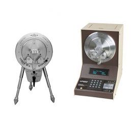
For test ranges 2 – 9, specimens are mounted on the Taber V-5 Stiffness Tester using a clamping system. Located on the pendulum, the lower faces of the specimen clamp jaws are exactly on the center of rotation.
This ensures a constant test length and deflection angle for accurate and repeatable results. Both jaws of the specimen clamp are adjustable, so the test specimen can be positioned precisely in the center regardless of material thickness. Force is applied to the lower end of the specimen by a pair of rollers. The rollers, which are attached to a driving disc located directly behind the pendulum, push against the test specimen and deflect it from its vertical position. The pendulum applies increasing torque to the specimen as it deflects further from its original position. The test point reading occurs when the pendulum mark aligns with the appropriate driving disc mark (7 1/2° or 15°), which points to the stiffness reading on the dial point. The final reading will depend on the range in which the test is being conducted and what scaling factor to use. The instrument outputs the moment load applied to the test specimen in TABER Stiffness Units (g · cm).
To allow the testing of materials with different stiffness properties, range weights can be applied to the pendulum. For extremely light weight materials, a compensator range weight is mounted to the top of the pendulum. Range weights of 500, 1000 and 2000 “Taber Units” are mounted to the bottom of the pendulum and required for stiffer materials. An optional range weight set of 3000 and 5000 Taber units is required for test ranges 7, 8 and 9.
Range 1 is used with Taber’s optional Sensitivity Range Attachment (also referred to as SR or High Sensitivity Attachment) to test extremely lightweight and flexible materials whose Taber Stiffness Unit value are between 0 – 1. Examples include cellophane, natural fibres and synthetic filaments, tissue paper, metallic foils, films, etc. The attachment includes two parts, the Driven Pins Holder which is secured between the clamp jaws, and the Driving Pins Holder which is mounted to the studs in place of the left and right hand rollers. Both parts include precision pins that are oriented horizontal to the face of the V-5 Stiffness Tester. A specimen 1 1/2″ x 1 1/2″ is mounted such that the second and fourth pins are above the specimen. As the driving disc rotates, the fourth pin of the Driving Pins Holder pushes down on the specimen while the first pin pushes up. As the sample is deflected, the Driven Pins Holder aligns the pendulum to the appropriate stiffness value. For Range 1, the specimen is only deflected to the right.
Many customers have also utilized the Taber V-5 Stiffness Tester to evaluate wire and cable stiffness characteristics. The tester now incorporates a “v-notch” in the clamps to accommodate this testing. Suggested samples are 70mm long and 3mm – 8mm in diameter, and centered in the notch with care so as to not pinch or crimp the sample. For wire and cable samples less than 3mm diameter, it is recommended to secure the sample at a location in the flat region of the clamp. Samples with curvature may interfere with proper set-up and function of the Stiffness tester and should be avoided. In addition, test results obtained should be used for comparison only – that is, between lots, between materials, etc.
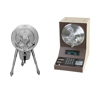
TABER Stiffness Tester – Model 150-E (115/230V, 50/60Hz) – Stiffness Tester Model 150-E features an on-board computer that automatically calculates and records stiffness testing data. Stiffness readings are automatically converted to the appropriate user-selected stiffness range, eliminating the need to manually multiply results by a scaling factor. This instrument also calculates average, standard deviation, and high/low readings. Using the 16 button keypad, operators have the ability to select the direction, deflection and number of deflection cycles. The instrument can also be operated in manual mode, similar to Model 150-B.
With the accessory ports, data generated with the Model 150-E Stiffness Tester can be either printed or downloaded to a PC. Plus, up to 1,000 readings can be stored in non-volatile memory. In addition to the internal real-time clock and calendar, stored readings can be identified with an optional user-defined label. To download data, an optional RS232 Serial to USB Adaptor Cable is recommended.
TABER Stiffness Tester – Model 150-B (110V, 60Hz) – The Model 150-B is a manually operated instrument, which is based on the original Taber V-5 Stiffness Tester. Mounted on telescoping tripod legs, the Model 150-B is lightweight for easy portability. Electronic components are sealed in a rugged housing. The model 150-B requires the user to manually record stiffness testing data, average the readings and multiply results by a scaling factor.
NOTE: Taber offers a step-down transformer (220V/110V) to operate the Model 150-B at 220V.
Evaluation
After the test material has been deflected 15° (or 7 1/2°) to the left and right, the average reading is determined. This is then multiplied using the number assigned in the Set-Up Chart for the particular range. The product is the stiffness value of the material measured in Taber Stiffness Units.
Taber Stiffness Units are defined as the bending moment of 1/5 of a gram applied to a 1 1/2″ wide specimen at a 5 centimeter test length, flexing it to an angle of 15°. A Stiffness Unit is the equivalent of one gram centimeter.
E = 0.006832 • (1/(w • d3 • θ)) • ST
Where E = Stiffness in flexure in pounds per square inch
w = specimen width in inches
D = specimen thickness in inches
θ = deflection of specimen converted to radians (15° = 0.2618 radians, 7.5° = 0.1309 radians)
ST = Taber Stiffness Units
Resilience is the elastic quality of a material expressed as the ratio of basic stiffness to initial stiffness, as determined with the following formula:
% of Resilience = (Basic Stiffness • 100) / Initial Stiffness
Initial Stiffness is the first reading obtained immediately when flexing the specimen to the end point of deflection (typically 15°), and is generally used for comparing relative stiffness qualities.
Basic Stiffness is the loss of stiffness caused by “elastic fatigue”, or the realignment of the molecules experienced by the material when a specimen is held at the end point of deflection.
As reported in TAPPI Test Method T543, Taber Stiffness Units can be converted to Genuine Gurley™ Stiffness Units with the below equation. The range of correlation test studies between Taber and Gurley stiffness values were from 20 – 150 g cm on Taber.
ST = 0.01419SG – 0.935
Where ST = Taber Stiffness Units
SG = Gurley Stiffness Units
To convert Taber Stiffness Units to Millinewton-Meters, use the following equation:
“X” mN-m = ST • 0.098067
Where ST = Taber Stiffness Units
To convert Taber Stiffness Units to Pound-Inch, use the following equation:
“X” lb-in = ST • 0.000868
Where ST = Taber Stiffness Units
The extreme sensitivity of the Taber V-5 Stiffness Tester magnifies variations in the material. Therefore, it is recommended that 5 or more samples be tested and the average result taken as the stiffness rating. Variations in testing may also result from the way in which the specimen is clamped or how clearances are adjusted between the rollers and specimen. It is important to note:
